


| About | Downloads | Publications | Contributors | Achievements |
| News |
|
2.12.2015 - Our new paper on simulation of Time-of-Flight and Phase Contrast angiography is now available on-line. We encourage you to read it.
30.11.2015 - In the Downloads section we've added a link to a Xcode project where we implement a vascular tree growth simulation algorithm. Have a try :-). 6.10.2015 - Two new models of the carotid artery bifurcation have been added to the downloads database. 15.08.2015 - We are starting a new project on magnetic resonance simulation. This time we will work on kidney perfusion modeling. More information soon. |
| Visit also |


|
| Visits counter |
|
Number of pageviews from 1/03/2015 |
Simulator validation using physical flow phantoms
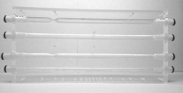
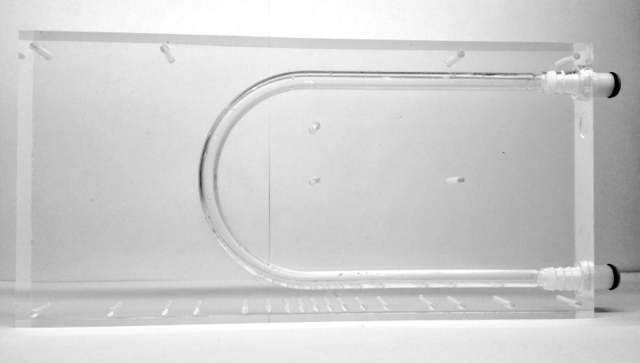
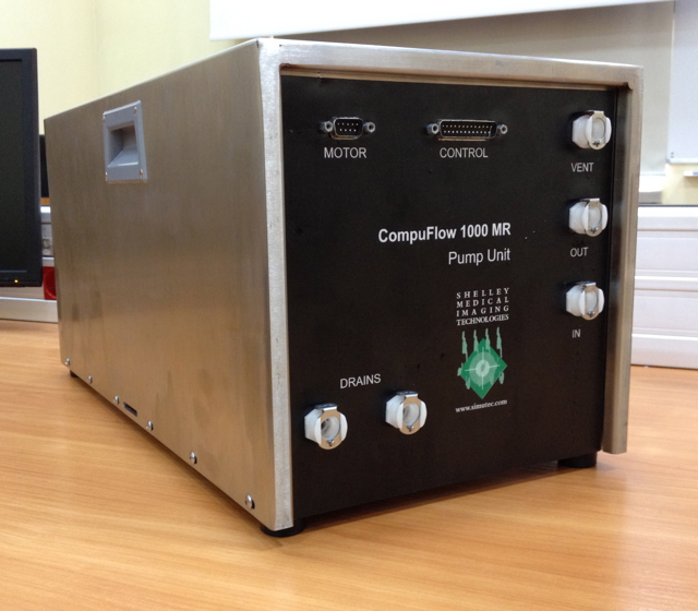
One of the most important tasks of the project was validation of the designed simulation system. This experiment was performed using physical phantoms of blood vessels, blood-mimicking fluid, and specialized MR-compatible pump manufactured by Shelley Medical Imaging Technologies.
|
|
|
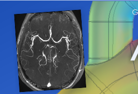
The flow phantoms set used in the project is primarily dedicated to MR scanners calibration and standarization. The details of the conducted experiments are given in this article. In the figure below, measured images can be compared against the simulated ones obtained for the digital phantoms, whose geometry was adusted to the physical ones. The corresponding images were compared quantitatively by calculating a correlation coefficient and RMS error. The obtained results (see the table below) as well as visual inspection of the images lead to a conclusion, that the designed framework is capable of synthesizing realistic MRA images, to a large extent consistent with the measured data. he synthesized images contain much of information found in the real ones. The most important image features reproduced in the performed simulations are as follows:
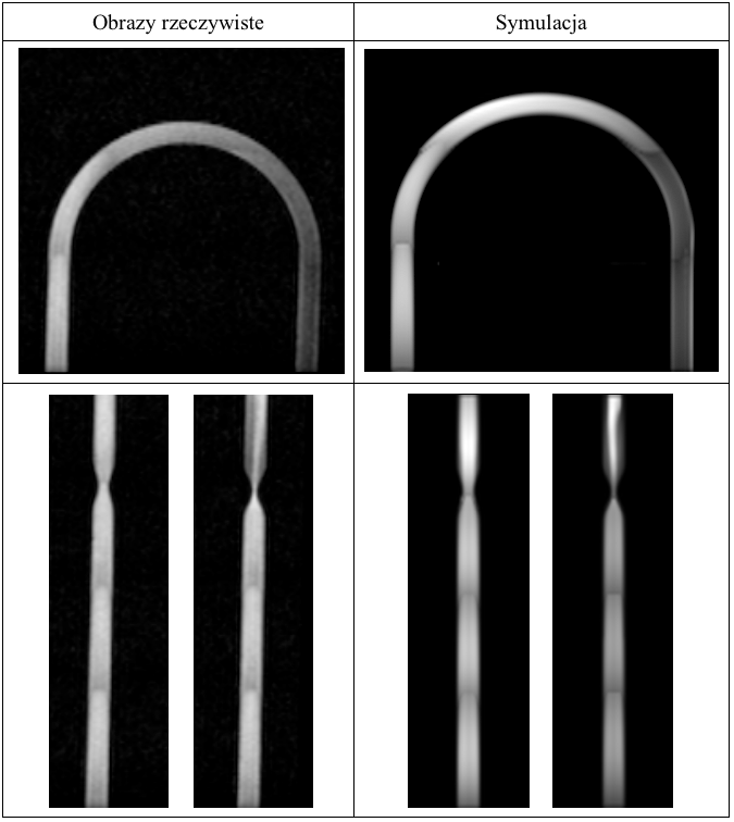
Example real and simulated for the relevant physical and digital flow phantoms
TR/TE/FA = 27/4.7/15° [ms/ms/-].
TR/TE/FA = 27/4.7/15° [ms/ms/-].
Quantitative comparisom of real and simulated images.
| Phantom |
Flow rate [ml/s] |
Correlation coefficient |
RMS error |
| U-band | 2.5 | 0.927 | 11.52 |
| 4.6 | 0.904 | 11.57 | |
| 10.0 | 0.811 | 13.24 | |
|
50%-stenosis channel |
2.5 | 0.918 | 12.01 |
| 4.6 | 0.911 | 11.89 | |
| 10.0 | 0.781 | 16.75 | |
|
75%-stenosis channel |
2.5 | 0.897 | 13.05 |
| 4.6 | 0.901 | 12.06 | |
| 10.0 | 0.875 | 13.97 |